Fuel Sender Types Supported
SkyView EMS modules support the following fuel level sender technologies:
- CiES Magnetoresistive Senders - High-precision contactless senders with voltage output
- Resistive Fuel Level Senders - Traditional variable resistance float-style senders (most common)
- Capacitive Fuel Level Senders - Capacitive plate systems with voltage output (0-5V DC)
- Other Capacitive Fuel Level Senders - Alternate non-float capacitive fuel probes with resistive output.
Prerequisites
- SkyView system with SV-EMS-220 or SV-EMS-221 module
- Fuel level senders installed and wired according to sender manufacturer instructions
- Access to fuel tanks for calibration
- Accurate fuel measurement containers (within 3% accuracy) or calibrated fuel scale
- Aircraft jacks and leveling equipment
- SkyView System Installation Guide (for reference)
- Sender manufacturer installation documentation (if available)
Step 1: Determine Your Sender Type and Pin Requirements
1A. Resistive Fuel Level Senders
Compatible Pins: Any General Purpose (GP) input pins: 4, 7, 9, 10, 11, 12, 20, 21
Recommended Pins: Pins 20 and 21 are recommended for fuel level senders before using other GP inputs. Additional tanks may use any remaining available GP inputs. (Can use EGP input(s) as a last resort)
Pin Configuration Path:
SETUP MENU > EMS SETUP > SENSOR INPUT MAPPING > C37 Pxx
PIN # = [Selected pin number]
FUNCTION = LEVEL
SENSOR = FUEL LEVEL (RESISTIVE)
NAME = LEFT, RIGHT, MAIN, CUSTOM (Max 6 characters)
1B. Capacitive Fuel Level Senders (Including CiES)
Compatible Pins: Enhanced GP inputs only: 8, 22, 23, or 31
Pin Configuration Path:
SETUP MENU > EMS SETUP > SENSOR INPUT MAPPING > C37 Pxx (8, 22, 23, or 31)
PIN # = [Selected Enhanced GP pin]
FUNCTION = LEVEL
SENSOR = FUEL LEVEL (CAPACITIVE) *or FUEL LEVEL (CIES) on newer firmware
NAME = LEFT, RIGHT, MAIN, CUSTOM (Max 6 characters)
- SkyView HDX (Firmware 17.5+) and SkyView Classic (Firmware 16.7.8+): The FUEL LEVEL (CIES) option is available and provides the same functionality as FUEL LEVEL (CAPACITIVE) with more descriptive naming for CiES installations.
- Earlier firmware: Use FUEL LEVEL (CAPACITIVE) for all capacitive and CiES senders.
- Only available on Enhanced General Purpose (EGP) inputs.
1C. Sensor Type Response Time Options
Beginning in SkyView Software v13.0 with Sensor Definition File Revision 46371 (2015-07-16 or later), you can choose response time characteristics:
For Resistive Senders:
- FUEL LEVEL (RESISTIVE) - Averages changes over 1.5 minutes (most change in first minute) - DEFAULT
- FUEL LEVEL (RESISTIVE FASTER RESPONSE) - Averages over 15 seconds (most change in first 7 seconds)
- FUEL LEVEL (RESISTIVE SLOWER RESPONSE) - Averages over 7 minutes (2/3 of change in first 3 minutes)
For Capacitive/CiES Senders:
- FUEL LEVEL (CAPACITIVE) or FUEL LEVEL (CIES) - Averages changes over a few minutes - DEFAULT
- FUEL LEVEL (CAPACITIVE SLOWER RESPONSE) - Averages over approximately 3x the time of standard CAPACITIVE
Step 2: Special Configuration for Van's RV Capacitive Plates
2A. Wiring the Van's Capacitance Converter
| Wire Color | SV-EMS Pin | Function |
|---|---|---|
| Black | Any of 5, 13, 16, 17, or 30 | Ground |
| White | Any of 8, 22, 23, or 31 | 0-5V DC output to EMS |
| Red | 15 | 12V DC Power (normally for fuel flow) |
2B. Van's Converter Configuration
- Connect the BNC Male connector on the converter to the BNC Female connector on the fuel tank
- Wire according to the table above
- Configure the white wire's EMS pin as FUEL LEVEL (CAPACITIVE)
- If the capacitive plates require their own calibration per manufacturer instructions, perform that calibration BEFORE performing the SkyView fuel level calibration
Step 3: Update Screen Layouts for Non-Default Fuel Senders
3A. Remove Default Fuel Level Widgets
SETUP MENU > EMS SETUP > SCREEN LAYOUT EDITOR
Select each layout percentage: BOTTOM STRIP..., 50%, 100%
Delete the existing fuel quantity widgets
3B. Add New Fuel Level Widgets
After configuring your fuel senders in Sensor Input Mapping, new fuel level widgets will become available in the Screen Layout Editor. Add these widgets to your desired screen layouts (BOTTOM STRIP..., 50%, 100%).
Step 4: Verify Sender Operation Before Calibration
Before proceeding to calibration, verify that each sender is producing valid voltage output:
- Navigate to:
SETUP MENU > EMS SETUP > SENSOR DEBUG DATA - Locate the pin where your fuel sender is connected and configured
- Monitor the CAL (V) and VALUE columns
- For accessible senders (external or bench testing), manually move the float arm through its full range
- Verify voltage changes smoothly from near ~0V/5V (empty) to near ~5V/0V (full) for properly oriented senders
- If voltage does not change or remains at 0V or 5V check wiring
⚠️ TROUBLESHOOTING: If voltage readings are erratic, unstable, or do not change with float movement:
- Verify ground connections (especially for capacitive/CiES senders)
- Check that Enhanced GP pins are used for capacitive/CiES senders
- Confirm correct SENSOR type is selected (RESISTIVE vs CAPACITIVE/CIES)
- Verify sender has power if required (CiES, capacitive converters)
- GP and EGP (RESISTIVE) inputs float at 5V with nothing connected
- EGP inputs configured for (CAPACITIVE/CIES) display 0V with nothing connected
Step 5: Prepare Aircraft for Fuel Calibration
5A. Level the Aircraft
- Jack the aircraft to the manufacturer's specified leveling attitude (typically level flight attitude)
- Use wing jacks if available to maintain level in the roll axis during single-tank filling
- Verify aircraft is level using manufacturer-specified reference points for both pitch and roll
- If wing jacks are not available, be aware that CG shift during filling may cause roll axis deviation
5B. Prepare Fuel System
- Completely drain all fuel from the tank(s) to be calibrated using necessary methods
- For aircraft with cross-feed capability, set fuel selector to OFF position to prevent fuel transfer between tanks during calibration
- Add the unusable fuel quantity specified in the aircraft Type Certificate Data Sheet (TCDS) BEFORE starting calibration
- Verify all drain plugs and sumps are properly secured
5C. Prepare Fuel Measurement Containers
- Use graduated fluid measurement containers accurate to within 3% of measured volume
- Do NOT rely on fuel pump dispenser readings - these are insufficiently accurate
- If measuring fuel by weight, accurately determine fuel density by type
- Have enough containers prepared to complete the entire calibration without interruption
Step 6: Perform Fuel Level Calibration
6A. Access Calibration Menu
SETUP MENU > HARDWARE CALIBRATION > EMS CALIBRATION
Select: FUEL TANK 1 (LEFT) or FUEL TANK 2 (RIGHT) or FUEL TANK 3 (AUX)
Select: CALIBRATE
The system will display the current fuel tank configuration and prompt you to begin the calibration process.
6B. Calibration Procedure
- Enter total known fuel capacity for tank being calibrated
- The system will calculate fuel pour increments based on your configured tank capacity
- You will be prompted to add fuel in equal volume increments (typically 8-10 calibration points)
- For each calibration point:
- Add the requested amount of fuel accurately using your measured containers
- Wait 30-60 seconds for voltage readings to stabilize (longer for capacitive senders)
- Press
ADDto record the calibration point - The system displays the current voltage reading for reference
- Note and write down the stabilized voltage reading for each calibration point
- Continue through all prompted fuel pours until the tank reaches full capacity
- After adding the final fuel pour and allowing voltage to stabilize, press
ADDone more time - Only after pressing
ADDfor the last calibration point, pressFULLto complete calibration - Review the calibration summary and select
SAVE
🚫 CRITICAL CALIBRATION ERRORS TO AVOID:
- Pressing
ADDbefore completing a fuel pour will corrupt the calibration results - Pressing
ADDtwice for a single fuel pour will create an invalid calibration point - Pressing
FULLbefore pressingADDfor the last pour will discard the final calibration point - Not allowing voltage to stabilize before pressing
ADDwill capture incorrect voltage values
If any of these errors occur, the calibration will be inaccurate and must be repeated.
6C. Handling Voltage Plateau During Calibration
You may reach a point where adding more fuel does not change the voltage reading. This occurs when:
- The float arm has reached its maximum physical travel limit
- Tank structure prevents further float movement
- The sender has reached its maximum output voltage (~4.7-5.0V)
6D. Calibration Failure Modes
The calibration process will fail and require restart if:
- Voltage readings move backward (decrease when they should increase, or vice versa)
- Multiple consecutive calibration points show no voltage change when fuel is actually being added
- Voltage readings fluctuate excessively between consecutive points
If calibration fails, check for:
- Poor ground connections causing voltage instability
- Float arm binding or obstruction
- Incorrect sender orientation
- Bad OEM sensor due to wear and tear from age
- Dead spots during float arm movement
- Power supply issues to active senders (CiES, capacitive converters)
Step 7: Review and Adjust Calibration Table
7A. View Calibration Results
SETUP MENU > HARDWARE CALIBRATION > EMS CALIBRATION > FUEL TANK 1 (LEFT)
Select: EDIT
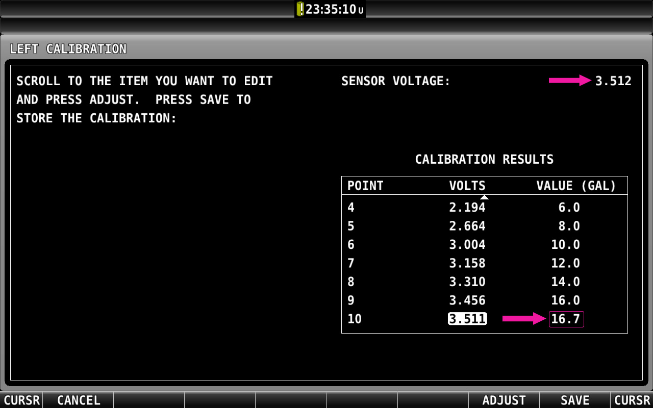
Scroll through the calibration table to review all recorded data points. The table shows:
- Fuel quantity (in gallons or liters)
- Corresponding voltage at each calibration point
- Calculated interpolation between points
7B. Determine Maximum Graphical Display Value
- Scroll to the bottom of the calibration table
- Note the highest fuel quantity value listed (e.g., 49.2 gallons)
- If you have multiple tanks, repeat for each tank and note each maximum value
- For symmetrical tank installations (left and right), determine the lower of the two maximum values
- Round this value DOWN to the nearest whole number (e.g., 49.2 becomes 49)
7C. Set Maximum Graphical Display
For each fuel tank:
SETUP MENU > EMS SETUP > SENSOR SETUP > LEFT LEVEL (or RIGHT LEVEL, etc.)
MAXIMUM GRAPHICAL DISPLAY = [Rounded down whole number from Step 7B]
Press: ACCEPT
For symmetrical tanks (left and right), set BOTH tanks to the same Maximum Graphical Display value.
Step 8: Configure Additional Fuel System Settings
8A. Set Alarm Thresholds
While in the Sensor Setup menu for each fuel level sensor:
SETUP MENU > EMS SETUP > SENSOR SETUP > LEFT LEVEL
ALARM = [Select appropriate alarm]
Configure low fuel warning thresholds based on your operational requirements and reserve fuel planning.
8B. Configure Graphical Display Ranges
Set the color-coded display ranges for fuel quantity gauges:
- MINIMUM GRAPHICAL DISPLAY: Typically 0 (or unusable fuel quantity)
- MAXIMUM GRAPHICAL DISPLAY: Set in Step 7C
- Green Range: Normal operating fuel quantities
- Yellow Range: Low fuel warning zone
- Red Range: Critical fuel level (if applicable)
8C. Fuel Computer Settings (Optional)
If using SkyView's fuel computer features, configure:
SETUP MENU > SYSTEM SETUP > AIRCRAFT INFORMATION
- FULL FUEL CAPACITY: Set to the Maximum Graphical Display value (or total usable fuel)
- PRESET FUEL CAPACITY: Optional quick-fill preset (e.g., for fuel tab fills at 3/4 capacity)
- FUEL ADDED DETECT: When set to YES, SkyView will prompt to adjust fuel computer if discrepancies are detected between physical senders and calculated fuel on power-up
- FUEL TANK REMINDER: Optional timed or quantity-based fuel tank switching reminder
Step 9: System Verification and Testing
9A. Functional Testing
- With tanks at known fuel levels (from calibration), verify display accuracy matches actual fuel quantity
- Add a measured quantity of fuel and verify display updates correctly
- For aircraft with multiple tanks, verify both tanks indicate similarly when filled equally
- Test that fuel quantity decreases appropriately during engine operation (if fuel flow sensors installed)
- Verify low fuel annunciations trigger at configured thresholds
- Test fuel quantity display updates during various aircraft attitudes (if accessible)
- Note that aircraft fuel indications may differ when aircraft is returned to normal ground pitch attitude
9B. Response Time Verification
Verify the selected response time (RESISTIVE/CAPACITIVE/SLOWER) provides acceptable indication behavior:
- Power up the system and note how long it takes for fuel quantity to stabilize
- For slower response settings, allow up to 7 minutes for full stabilization
- During flight, verify fuel indications don't fluctuate excessively during maneuvers
- If indications are too slow or too fast for your operation, adjust the SENSOR type selection and re-test
9C. Failure Mode Testing (CiES and Powered Senders Only)
For senders that require power (CiES, capacitive converters):
- With the system powered and displaying normal fuel quantities
- Pull the circuit breaker providing power to the fuel senders
- Verify fuel displays indicate Empty or 0 gallons (NOT Full)
- Reset the circuit breaker and verify normal indications return
Step 10: Document Calibration
Create a calibration record including:
- Date of calibration
- Aircraft registration and serial number
- Fuel sender type and part numbers
- EMS module pin assignments
- Calibrated maximum fuel quantity for each tank
- Maximum Graphical Display values configured
- Fuel type used for calibration (important for capacitive senders)
- Any deviations or observations during calibration
Tips for Successful Calibration
- Utilize external power: This prevents the aircraft main battery from draining too low during the process
- Keep a written log: Record fuel quantities and voltage readings during calibration in case of failure or system issues. Dynon can utilize these quantity and voltage readings to adjust settings files
- One tank at a time: Complete calibration for one tank fully before starting another
- Stable environment: Perform calibration in stable temperature conditions; avoid direct sunlight on tanks
- Multiple people: Having a helper to pour fuel while you monitor the display improves accuracy
- Pre-measure fuel: Pre-measure all fuel quantities when possible before starting to avoid delays during calibration
- Allow stabilization time: Capacitive senders may require 60+ seconds to stabilize; resistive senders typically stabilize in 10-30 seconds
Troubleshooting
| Issue | Possible Cause | Solution |
|---|---|---|
| Display shows "CAL ?" instead of fuel quantity | Fuel tank not yet calibrated, or voltage reversed during calibration procedure | Perform fuel calibration procedure (Steps 5-7). Ensure sender is properly configured in Sensor Input Mapping first. Contact Dynon if voltage reversed. |
| Voltage does not change during calibration | Float arm bound, incorrect wiring, incorrect sensor configuration, or sender failure | Check SENSOR DEBUG DATA for voltage output. Verify wiring connections. Check float arm for obstructions or binding. Verify sender power (if required). Verify proper sensor type configured. |
| Calibration completes with voltage moving backward | Usually results in "Cal ?" displayed over fuel level widget | If non-linear voltage is encountered during the calibration process, it's usually shown as a warning. Accepting this warning and proceeding with the rest of the calibration will result in an unusable calibration. |
| Erratic or unstable voltage readings | Poor ground connection, lose sensor termination, or electromagnetic interference | Verify ground resistance <0.3Ω to battery negative. Run temporary jumper to battery ground to test. Relocate ground to better point. Verify secure ring terminal and integrity of sensor wire from one end to the other. Check for nearby sources of EMI. |
| System indicates Full when sender loses power | Capacitive/CiES sender on standard GP input or wrong sensor type | Rewire to Enhanced GP input (8, 22, 23, or 31). Configure as FUEL LEVEL (CAPACITIVE) or FUEL LEVEL (CIES), NOT RESISTIVE when possible, or verify CiES sender power and wiring. |
| Fuel indication never reaches Full | Maximum Graphical Display set higher than calibrated maximum | Review calibration table maximum value. Set Maximum Graphical Display to calibrated maximum (rounded down). |
| Left and right tanks show different values when filled equally | Different Maximum Graphical Display values or poor calibration | Set both tanks to same Maximum Graphical Display value (use lower of two calibrated maximums). Verify aircraft was level during calibration, and that fuel selector didn't allow cross-feed. |
| Fuel indication takes 5-7 minutes to stabilize after power-up | SLOWER RESPONSE option selected, or power applied to SkyView before capacitive senders | Change to standard FUEL LEVEL (CAPACITIVE/RESISTIVE) response. OR change startup procedure to power senders before SkyView. |
| Fuel indication significantly inaccurate after fuel type change | Capacitive senders calibrated for different fuel type | Capacitive senders must be recalibrated when fuel type changes (especially ethanol content). Use only the fuel type for which system was calibrated. |
Important Safety and Operational Notes
🚫 SAFETY REMINDERS:
- Fuel level indication systems are supplementary instruments and should not be the sole means of fuel quantity determination
- Always conduct preflight fuel checks using visual inspection and fuel dipsticks per aircraft manufacturer recommendations
- Maintain awareness of fuel consumption rates and flight duration as primary fuel management methods
- Fuel level senders can be affected by aircraft attitude, fuel slosh, temperature, and other factors
- Regular recalibration may be required per aircraft maintenance schedule or if indication accuracy degrades
- For capacitive senders: ONLY use the fuel type for which the system was calibrated; placard aircraft accordingly
Reference Documents
- SkyView System Installation Guide - EMS Configuration and Calibration sections
- Fuel sender manufacturer installation instructions
- Aircraft Type Certificate Data Sheet (TCDS) - for unusable fuel quantities
- Aircraft Flight Manual / Pilot Operating Handbook - for fuel system specifications
- CiES Fuel Level Sending Units - Installation and Configuration for SkyView (for CiES-specific guidance)